Advanced WebArchitect features (system-specifics)
Cabling
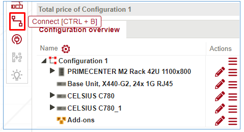
Connection view can be opened with “Connect” button at Action Panel
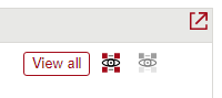
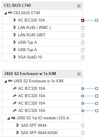
At top right you can select 2 mode: “view all” or “view selected”. Select “View all” – to see all systems in Connection view. “View selected” – to see just chosen at configuration overview systems.
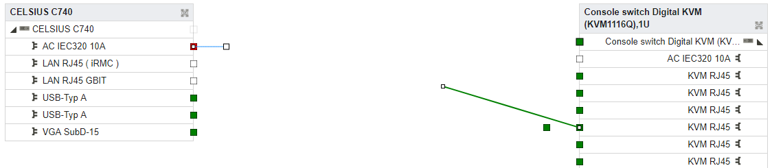
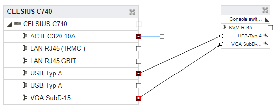
When you select some connector then available to connection connectors will be marked with green color.
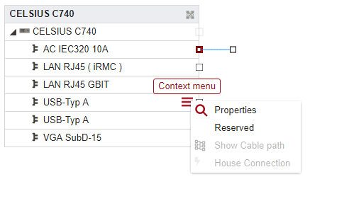
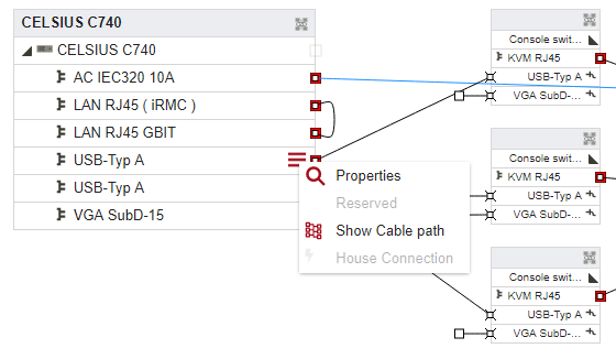
You can Reserve some connector for your purposes with Context menu.
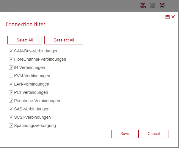
At the top right you can click on “Connection filter” icon to show definite type of connections.
You can see just some selected cable in Context menu with function “Show cable path” in Context menu.
Connecting cables
A connecting cable is supplied with the product. It has no price of its own, since it is included in the price of the product. Unlike normal cables, it does not have its own order number. Connecting cables can be fixed or detachable. Fixed connecting cables cannot be deleted.
Adapters
Adapters are a special type of cable.
They have plugs and sockets.
They can have multiple sockets or plugs.
Plugs and sockets have different types / designs
Multi-level connections
If two connectors are connected to each other by a series connection of several cables or adapters, this is termed a multi-level connection.
Components handling
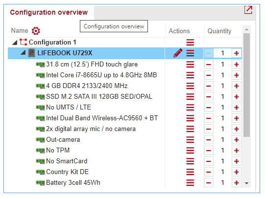
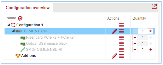
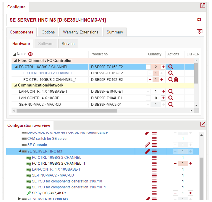
All components added are shown in Configuration overview.
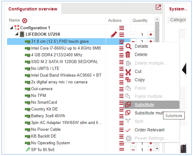
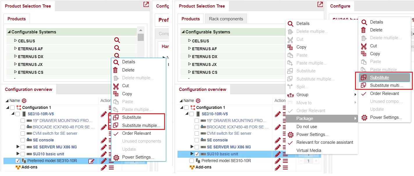
Substituting components
If there are another components exists it is possible to substitute. Press context menu and select Substitute.
Possible Substitution are shown
Components can be searched using search bar. Enter part of the component name or product number to search for. Use an asterisk (*) during search to replace any string of characters. Found matches will be highlighted with yellow. Use arrows to navigate between the search results.
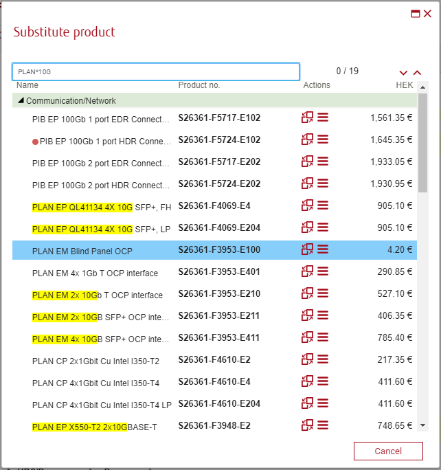
After pressing Substitute button component is changed
Searching for components
For searching components use “Advanced search”. Description for this functionality can be found in section “Advanced Search”.
Prices of components
Price settings are available in Settings menu. List of available prices depends on user rights.
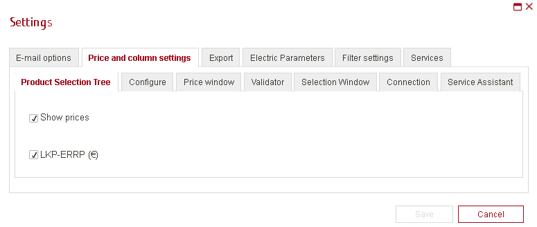
If ‘Show prices’ selected prices are shown in appropriate section.
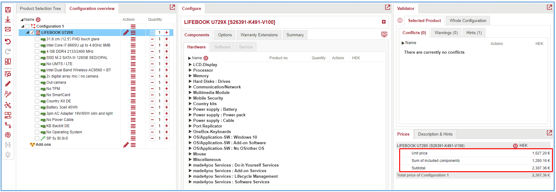
Selected component price is shown on Prices desk
Automatically added components
Once system is selected, popup with automatically added components is shown.
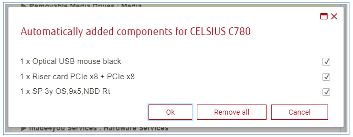
For saving without such components press ‘Remove all’ and ‘Ok’.
Note: Some of systems does not have such components. In this case popup isn’t show.
Graphical arrangement of components
Graphical arrangement works only for Racks.
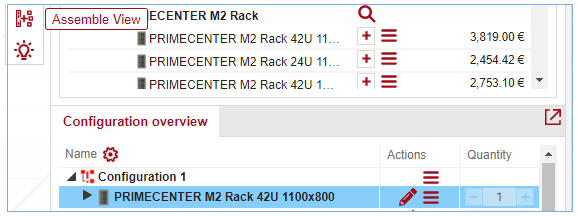
Add some Rack configuration from Product selection tree. Press Go to assemble view from left menu.
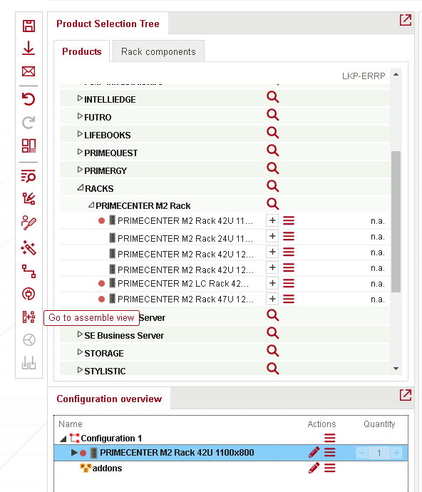
‘Rack components’ is shown on Product Selection section. Assemble tab is opened.
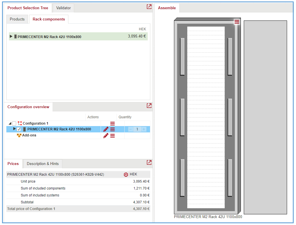
Components added from menu ‘Rack Components’ are shown in Assemble view:
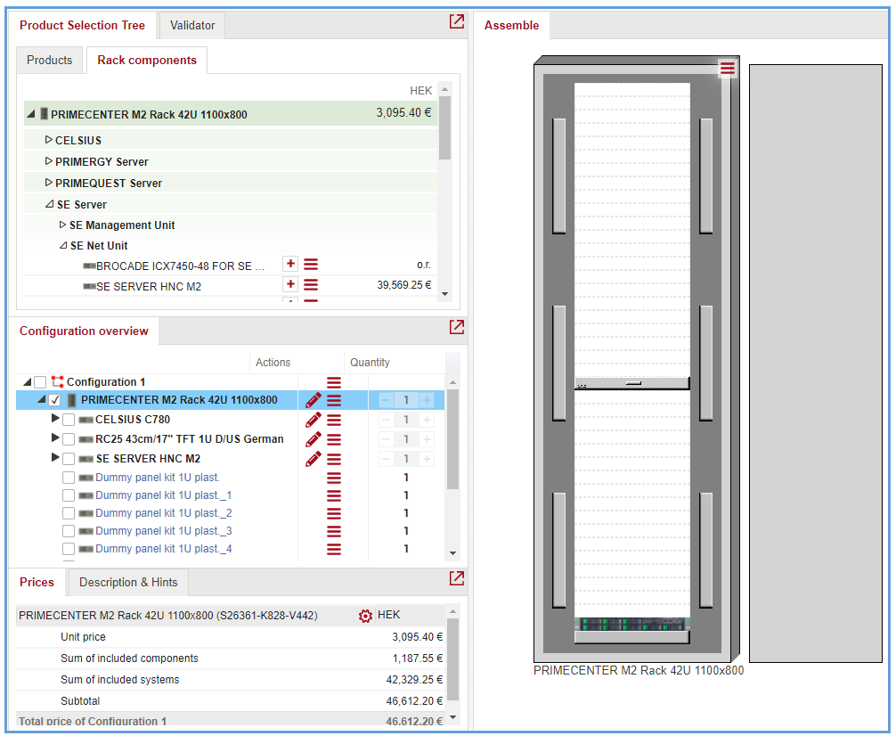
It’s possible to move components inside Rack or move out of Rack (on to Parking zone) by ‘Drag & Drop’:
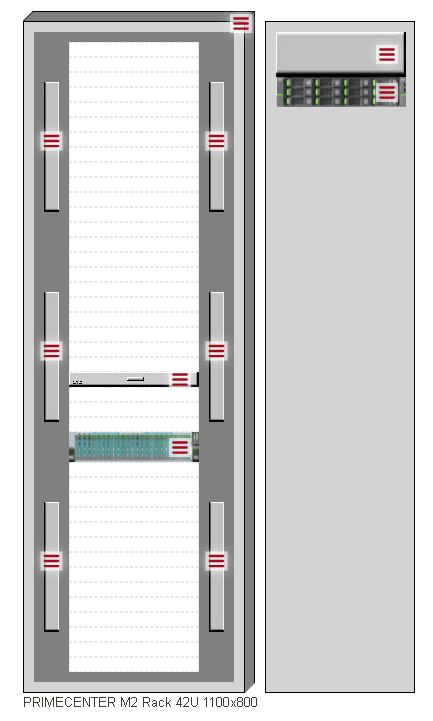
Some of components are added by group. In this case there is yellow border around items:
For moving such elements you need to drag by pressing on the yellow corner.
Grouping components and systems
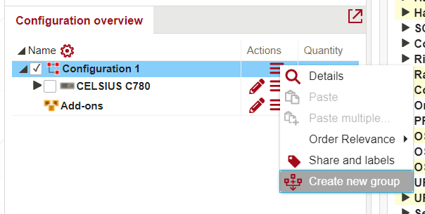 New way of creating a User Defined Groups: From now, users are able to create a groups not from system Context menu, but from Configuration Context menu.
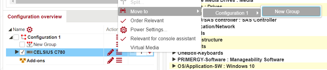 In system Context menu is now presented function Move to, which allows to Move system to a created group, which was created in Configuration Context menu.
New group added are shown.
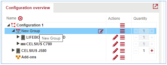
To change the name of the group, click on ![]() icon and type a new name inline:
icon and type a new name inline:
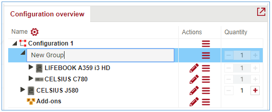
Click anywhere outside the edit field to save the changes.
Once created, the group is shown in a list under Group-> Rearrange hamburger menu item
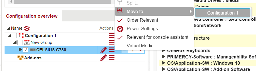 To ungroup items, select “Move to” item from context menu.
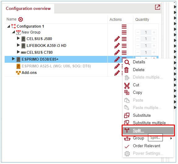
Besides grouping, multiple systems can be split too – see Fehler! Ungültiger Eigenverweis auf Textmarke.
Splitting components and systems
Splitting is working only if quantity of component is more than 1. Select Split from context menu.
Split window contains scale for choosing split settings.
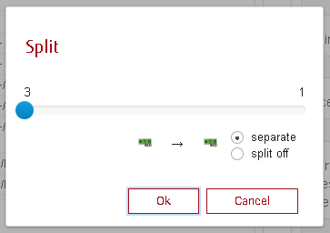
If you select 1 in one of sides components will be split to 1 and to rest of count. For example, if count is 4, and you select 3 and 1, then there will be 2 new rows – 1 and 3.
Next setting is choosing ‘Separate’ or ‘Split off’ Components splits.
For example if 2 and 2 selected in case above, and ‘separate’ selected then components are split to 2 and 2. In case if ‘Split off’ is selected then 3 rows appear: 2,1 and 1.
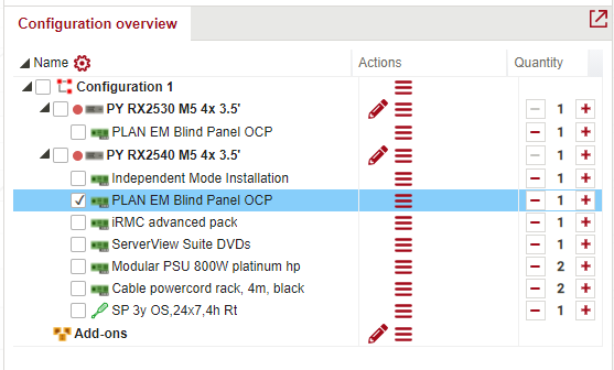
Copy elements of configuration by drag&drop
To easily copy items in configuration overview, such as components or systems, use drag&drop + CTRL key.
For example, it’s needed to copy component from one system to another:
Click on component, hold down the CTRL key and drag&drop component to another system.
DX assistant
DX assistant allows the configuration of storage system by setting the needed characteristics only. A selection of specific components is not necessary.
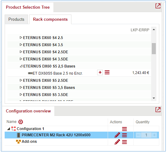
DX Assistant tab is normally available for DX/AF system’s core component – controller enclosure (CE). In other words, DX system configuration should not start with a drive enclosure (DE) or frontend enclosure (FE) – but with a CE.
In case DX system comes with a rack, the Base rack must be added first. Second, from “Rack components” tab an appropriate CE should be selected:
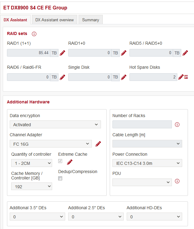
You can start configuration of storage systems starts with defining required storage capacity and RAID variant.
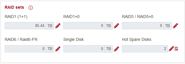
Use the pencil button to add volumes under necessary RAID variant(s). Amount of Hot Spare Disks is calculated automatically, but can as well be increased.
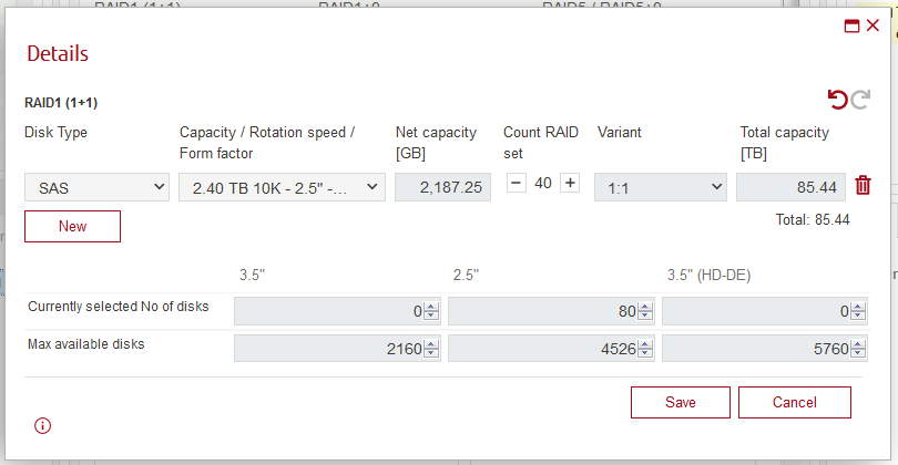
Multiple entries can be added, with drive (Capacity / Rotation speed / Form factor) as the main parameter. RAID variants and counts act as multipliers. Drive total counts are shown in the bottom of the RAID Details window.
Selected drives and RAIDs influence minimal necessary drive enclosures (and further controller enclosures too). Next window is about technical details of Controller Enclosures, not about volume storage system provides.
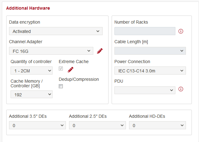
Cache Memory / Controller – is amount of RAM installed to every CE (it is per CE, not for the whole system – mind 8X00 systems)
Dedup/Compression flag – is an option allowing advanced optimization of data saved, as well as affecting minimum necessary memory per CE
Channel adapter – (earlier Host Interfaces) – sets network interfaces, enabled in the storage system. Their selection affect ability of storage to act as SAN / NAS or Unified .
Adjusting Quantity of controller (for Large systems only) – allows addition of extra CEs;
when Additional 3.5” / 2.5” / HD-DEs – sets extra enclosures, supplementary to minimal necessary counts for RAIDs
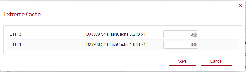
Extreme Cache is an options on it’s own – it configures SSD drives, used as additional quick cache. It is a per system level (not per CE)
Power Connection dropdown allows choosing type of cable to include – either to a regular wall socket or to a data centre socket strip. In case when used in APAC environment and inside the rack, choosing IEC cables activates PDU dropdown:
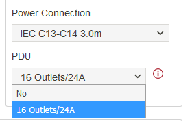
where one can choose adding PDUs into the rack. Number of necessary PDUs is calculated automatically.
Further, necessary software components can be configured (with corresponding licenses added into a configuration):
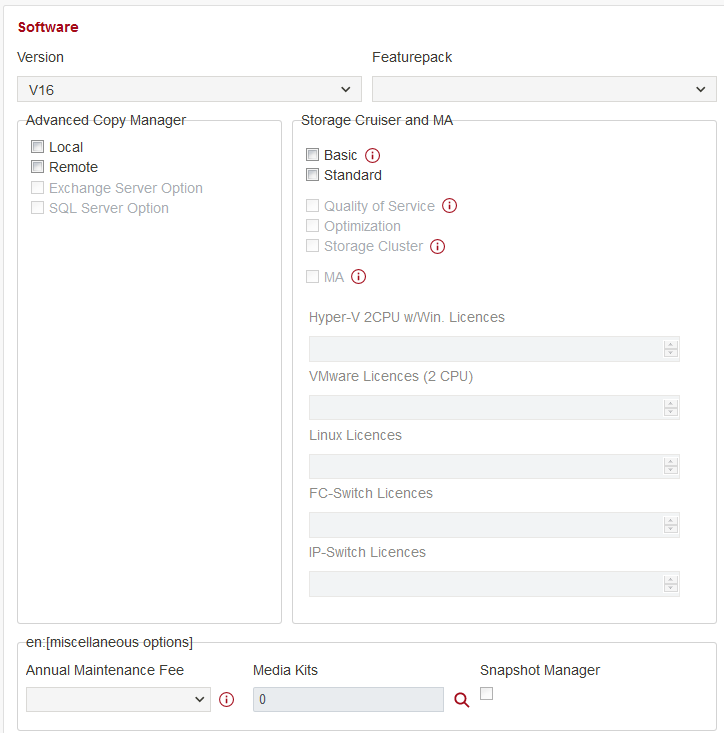
Annual Maintenance Fee can be added for up to 5 years.
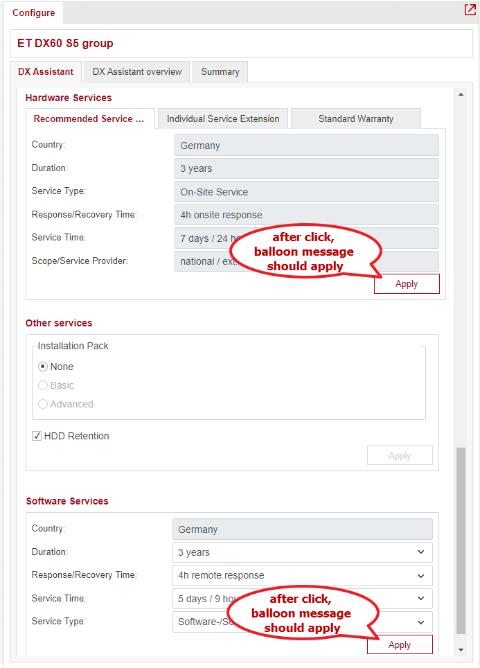
Last part of the Assistant is regular Services configuration; including Hardware, Software and Other services.
When a service is added or substituted in the DX Assistant by clicking the "Apply" button,
the user does not receive any feedback from the WA that this action was performed.
Therefore a balloon message should be displayed in this case.
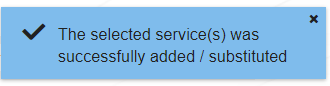
Balloon message: The selected service(s) was successfully added / substituted.
Groups
Please see paragraph 5.2.6
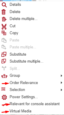
Order relevance
Order relevant (OR) product – product that user want to order.
Not order relevant (NOR) product – product that user don’t want to order, but he wants to order some of product’s component
Call order relevance function
All products are marked as order relevant by default.
Open context menu for a product in Configuration overview and select “Order Relevant” option:
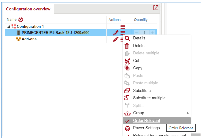
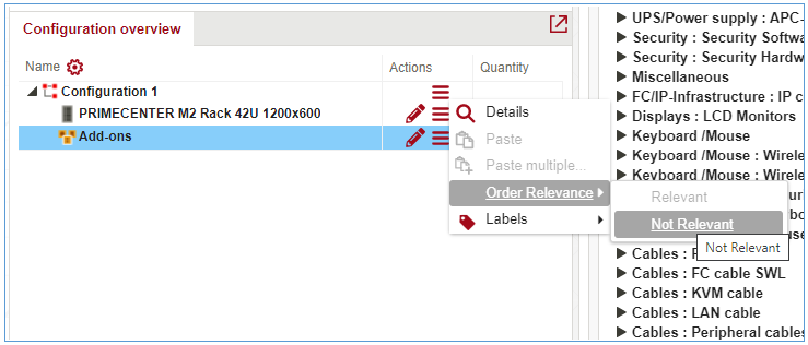
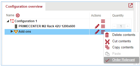
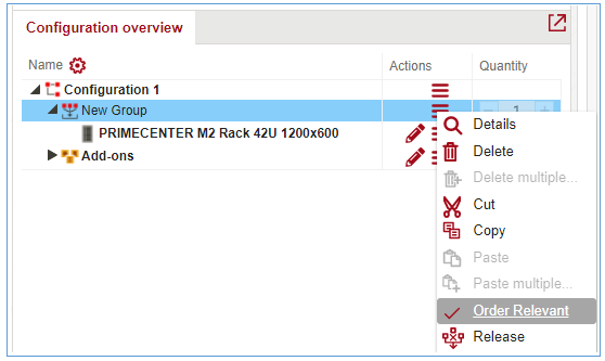
Order relevance function can also be called for whole configuration, add-ons node, user defined and extended groups from context menu:
NOR products properties
NOR products and sub nodes have pale shade in all places where they are shown:
The price of NOR products is equal to 0.
Its built-in components remained as built-in NOR.
Built-in components that don’t have an option to mapping can’t be added to NOR system or product, so they are disabled in components grid. If such components are already added to system, quantity of components can’t be increased.
When a new component is added to the NOR system or configuration, the component is added as OR.
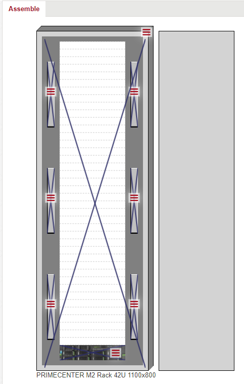
If rack marked as NOR, it has purple cross in assemble view:
Export settings
On the Export tab in the application settings there is “Show not order relevant components” flag.
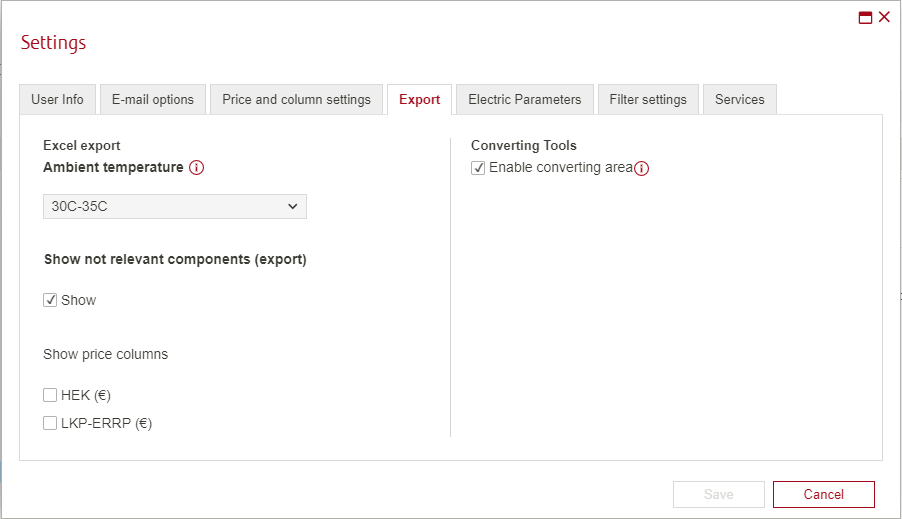
Check “Show” flag to display NOR components in the excel file.
Uncheck “Show” flag to prevent NOR components being displayed in the excel file, but note that configurable components and built-in software components will be shown even if the “Show” flag is unchecked
Packages and solutions
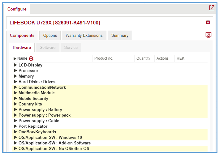
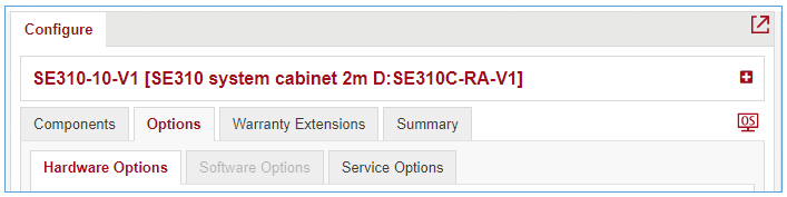
Configure
You can configure a package, if a package has defined model.
Click on a pencil near a package in configuration overview
WA shows Configure frame with opened “Options” tab. The tab should contain options that are assigned to the model.
“Components” and “Warranty extensions” tabs – are disabled
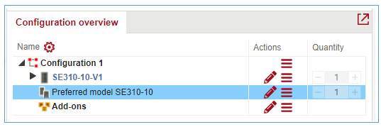
Add option to configuration
WA shows added option in “Summary” tab for package and adds option as package’s sub node in configuration overview:
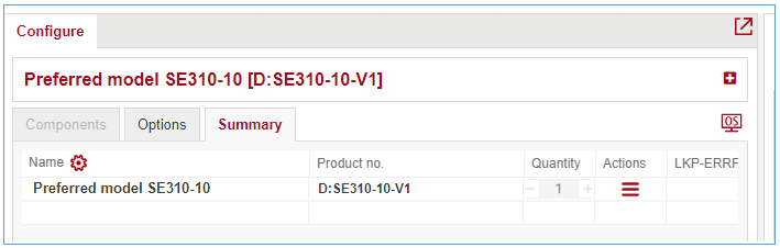
Options have their own prices.
Change quantity
If you want to change the quantity of a packages member you need to increase/decrease its amount in components grid, when package is assigned to a system and system has assigned at least one component with the same product number as package’s member.
Open “Components”/ “Options” tab in “Configure” frame for configurable system
Find a component that has the same product number as package’s member at top level and increases package’s amount (even if the component is excluded by another component)
WebArchitect will add each package as a separate line in “Configuration overview” frame
The quantity of a solution and package cannot be changed.
The quantity of systems and groups in a package/solution cannot be changed.
Cut, copy
Cut and Copy functions are available for package/solution node or products related to them and can be called from context menu.
Paste, multiple paste
When cutting/copying a product from the top level of a package/solution or package/solution node, the product is inserted as a package/solution.
When copying not all products from a package/solution, they are inserted into the configuration without a package/solution.
When cutting not all products from a package/solution, they are inserted into the configuration as a member of this package/solution
Substitute, multiple substitute
If product model (or related model) contains several packages/solutions into it, then we have ability to substitute one package/solution by another one. It’s possible to substitute package or solution via top-level member (at the bottom at configuration overview). Or via members of package/solution - Package/Solution item in Context menu.
Unused components
“Unused components” function can be called from context menu of a package.
This option is available when some of package members marked as unused.
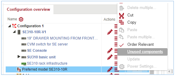
To mark a package component as unused, open the context menu and select “Do not use” function.
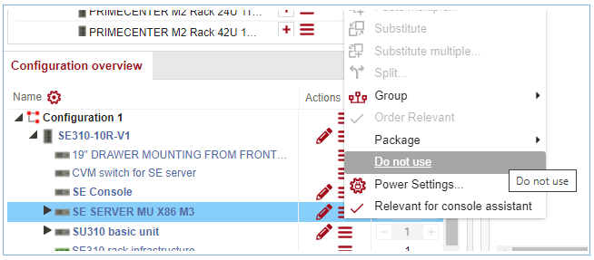
By calling this option, product is removed from everywhere (like deleted product) besides “Unused components” view and excel export. When product marked as unused, its cables and components (besides blue components) are deleted.
Prices
Price window is interactive and the content of it changes according to currently selected product or component.
Selectable products:
System
Component
Cable
Available for selection places:
Configuration overview
Product selection tree frame
Search results frame
Validator frame – only products that resolve conflicts/warnings/hints
Assemble frame
Connection frame
Choosing components for cabling popup window
Choosing cable popup window
Insert partition unit popup window
Popup window with recommended components
Substitution popup window
Multiple substitution popup windows
Advanced search popup window
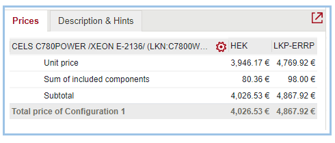
The price of package/solution is shown as for other products according to user settings.
Package’s price:
Package itself should has its own Unit and Total prices
Products that are marked as recommended should have their own Unit and Total prices
Products that are not marked as recommended have 0.00 Unit and Total prices
Solution’s price:
Solution itself has 0.00 Unit and Total prices, when it was added to configuration
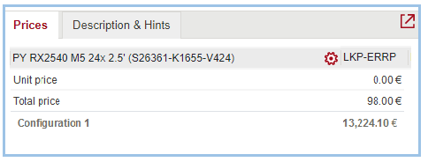
Solution itself has 0.00 Total price and Unit price = sum of mandatory products of solution, when the solution was not added to configuration, i.e. when price is checked for a solution in a product selection tree/advanced search/simple search results/selection assistant results
All products have their own Unit and Total prices
User is able to manage columns in Price window (see 3.3.1 Manage columns in configuration overview).
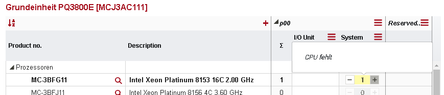
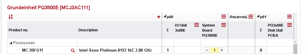
Partitions
Partitioning view is available only for part of systems (for example Grundeinheit PQ3800E).
Once system is added click on icon for partition from Action Panel.
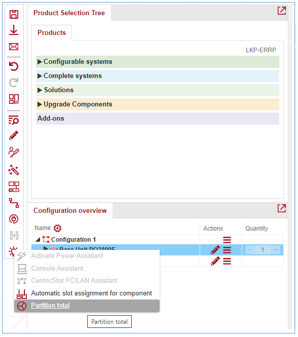
Partition view is opened.
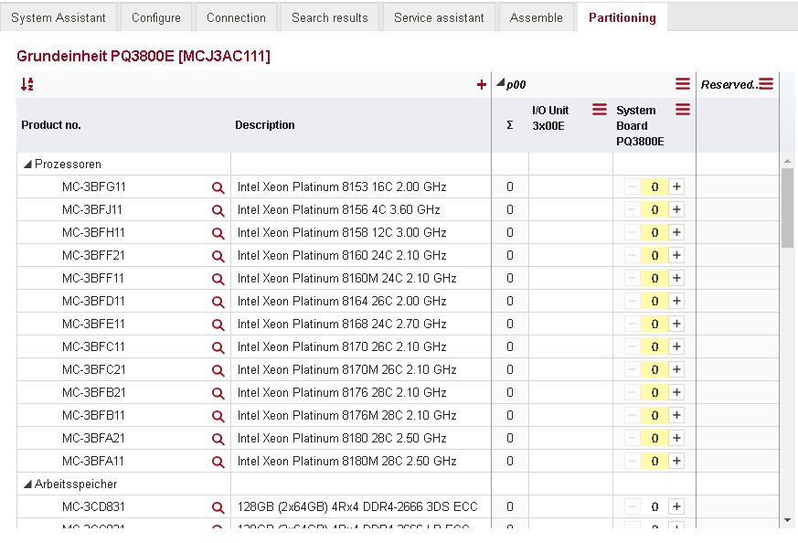
Partition view contains 2 partitions by default:
- P00. If system have configurable blue components, it contains 'Σ', 'I/O Unit' and 'System Board' columns.
- Reserved SystemBoard. It doesn't contain any columns
Items for System Board can be added by pressing ‘+’ on appropriate column. The quantity of component is changed from 0 to 1 in 'Σ' column
It’s possible to Insert Systemboard unit to partition via Context menu
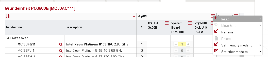
Inserted Systemboard can be moved to new or existed partition
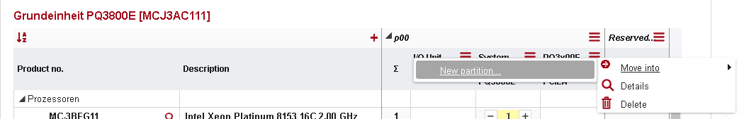
If ‘New partition’ is selected popup ‘Add new partition’ is shown.
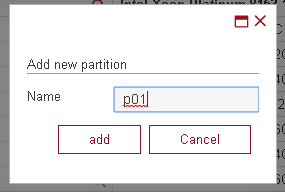
Once it’s done, system is moved to new partition.
Racks
Racks are used to accommodate several systems and could be found in “Rack” family.
Open Assemble view for a rack with “Assemble” button at Action Panel
When Assemble view is started then tab “Rack components” is automatically activated in Product Selection Tree. Now it’s possible to add products into Rack with “+” button or with “drag & drop”.
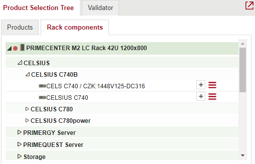
The selection is influenced by the selected rack. If multiple racks are shown in the assembling view, what is offered in the "Rack components" tab may differ, depending on the selected rack.
The position of components in the rack can be changed by moving them (left mouse click o and hold on the element, then move it to the new place and release the mouse button).
In addition to the height rules, it is recommended to place heavy components in a rack as far towards the bottom of the rack as possible, in order to make them easier to mount and to avoid tilting.
The context menu function "Fixed Position" can be used to prevent a positioned rack module from being moved.
Parking zone
Parking zone is a gray area surrounding every rack where rack modules can be temporarily stored (parked).
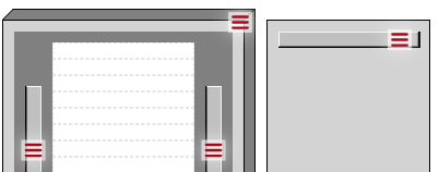
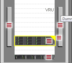
Dummy panels
In general, unused areas of a rack must be closed by dummy panels in order to prevent overheating of the components.
The necessary dummy panels are added permanently in the background without the user noticing this. A list of all automatically added dummy panels is created for every export and whenever the rack is saved. If required, however, dummy panels can also be placed manually like other rack components.
Rack in rack
Certain rack modules (blade server frames, retaining base plates, etc.) permit further internal assembly, without any change to the height units required in the base component.
Service Assistant
Service assistant is an enhancement over “Warranty Extensions” functionality – see paragraph 3.3.5 in this document. Worth noting, that Warranty extensions are offered only in a limited number of regions.
The assistant in called through “Configure Services” button from the action icons bar on the main screen:
![]()
Service assistant opens as a separate tab. On the right side you can set up filters to look for a service. It allows you to search for the correct service for a particular configuration.
Contrary to the flat list of possible service package, Service Assistant allows you to choose proper service package based on their attributes. Every attribute appears as a “filter” in the Service assistant tab.
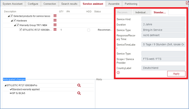
Three sub-tabs here are:
Standard Warranty
Recommended service extension
Individual service extension
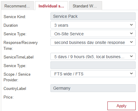 These are 2 presets (Standard and Recommended) and one flexible option over the same set of service attributes:
Service Kind – Service Pack or Top-up Package
Duration – 3 or 5 years
Service type – on-Site / other
Response and Recovery time – 4 hours / next day / second day response etc
Service time – 5*9 ; 7*9; 7*24 etc
Scope and Service provider – local or global
etc
Changes made in filters area are reflected in “Anticipated change” area in the bottom of SA tab:
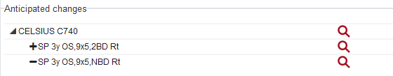
indicating current (-) and to-be (+) Service packages for the corresponding components. Only “Apply” button makes changes effective.
Service Assistant allows simultaneous configuration of more than 1 system/component from the overview:
When a service is added or substituted in the Service Assistant by clicking the "Apply" button, the user does not receive any feedback from the WA that this action was performed.
Therefore a balloon message should be displayed in this case.
Balloon message: The selected service(s) was successfully added / substituted.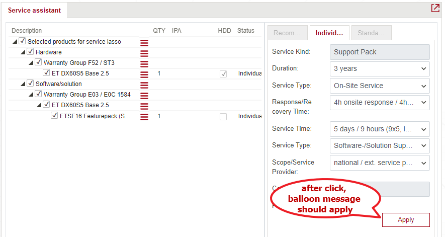
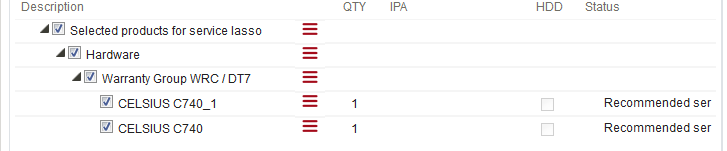
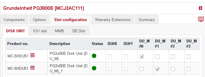
Slots
Slots need to be configured only for some part of systems (for example Grundeinheit PQ3800E).
Once system is added tab ‘Slots configuration’ becomes available.
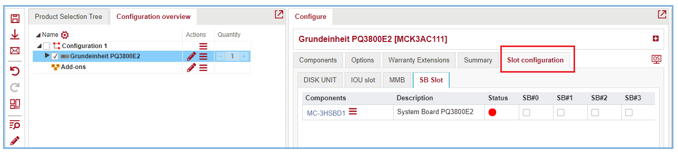
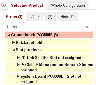
If there are no components added, table is empty. If you add something for configuration, slots issues will be shown in Validator under “Slots problems” on Errors tab:
It is possible to add several components via Components tab. Components added are shown now in a corresponding tab:
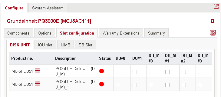
There are checkboxes for each slot. If there is no selection, Status is shown as red. Select some of available checkboxes.
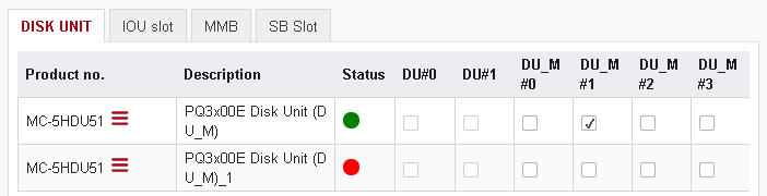
Status is changed to green. Each component should have different slots. So checkbox in selected column becomes disable for another components. For changing selection uncheck slot assigned and select another one.
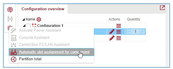
Also it is possible to assign slots automatically. Select component and click on icon “Assistans/Special functions” - “automatic slot assignment for component” from Action Panel.
Confirmation screen is shown:
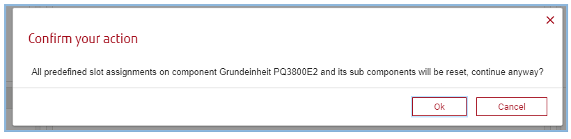
Press Ok and automatic assignment will be applied.
FC-LAN assistant
Cabling assistant for CentricStor
Configuration of CentricStor (CS) solutions has only been possible since packages have been available. Because these packages can in principle be expanded by the user (addition of ICPs, IDPs, TVCs, etc.), it makes no sense to have cabling that is already included in the package because it would always be incomplete. Consequently, no cabling is contained in the CS basic packages. It has to be carried out manually by the user after the configuration has been expanded by hardware. The cabling assistant for CS has been implemented to offer support for the complex FibreChannel (FC) and LAN cabling.
Function description
The cabling assistant only has an effect on groups.
One or two groups can be processed simultaneously.
Only new cabling, and not incremental cabling as in the power assistant, is supported.
Automatic FC and LAN cabling is carried out for all relevant components in the group. Firstly, redundant FC cabling is carried out, followed by non-redundant LAN cabling.
Connection of all CS processors and TVCs to the switches (FC and LAN)
Adding of all the additionally required switches and GBICs (FC)
Interconnection of the switches (FC and LAN)
Existing cabling is disconnected; the existing cables are reused where technically possible.
All additionally required components are added and cabled by the assistant.
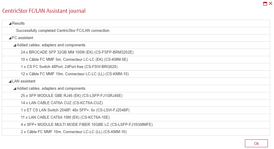
A detailed journal listing all the added components is generated.
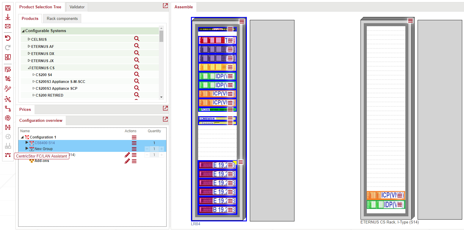
Start the assistant
The assistant jointly processes all racks and the components in them within a location. These are combined in groups. That means the function can only be started if one (or two) groups have been selected.
If one group is selected, internal group cabling is carried out.
If two groups are selected, they are first cabled internally and then connected to each other.
To call assistant, select one or two groups at configuration overview and then at Action Panel click on FC/LAN assi:
Connect within a group
If one group is selected, only internal group cabling is carried out. This is described later in this section.
Connection of 2 groups
If 2 groups are selected, the assistant creates additional connections between the leading racks of the respective groups. Since the distance between the groups is not included as a feature in configuration, an additional query is issued in this case.
Local cabling
This must be selected if the two groups are at one location, in the same room and arranged beside (in the direct vicinity of) each other. The options for long distance cabling are then disabled.
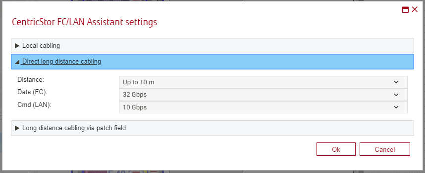
Long distance cabling
This must be selected if the two groups are not in the direct vicinity of each other. The distance is greater than 10m. In this case, the redundant FC cabling requires 2 FC switches in each group. These are added if necessary. With this cabling type, the options for long distance cabling must also be selected.
Uplink using patch field
If this option is enabled, the two subsequent options are disabled.
The option "Uplink using patch field" has the effect that no connection is carried out between the groups because there are already customer patch fields installed at the two locations of the group. Since the connections available there are not known, the components are selected manually in this case. The appropriate GBICs must be selected in both groups for the FC and LAN switches existing there. The correct FC cables are selected under Add-on products - Hardware - Cables - FC cable.
Use FC cables provided by Fujitsu Technology Solutions
This must be selected if FC cables that can be ordered directly from Fujitsu Technology Solutions are to be used for long distance cabling of the two groups. In this case, they are also added automatically by the assistant. The distance must be specified as described below so that the correct order number is determined. If the actual distance is outside the value range, Fujitsu Technology Solutions does not offer an appropriate cable, meaning the cable must be requested from an external vendor. In this case, please deactivate this option.
Distance
Enter the distance (in meters) between the two groups here. The value range is checked directly after this is done and a message is output if applicable. This option is only available if the required FC cables are to be procured directly from Fujitsu Technology Solutions and so become part of this configuration (see the previous option).
Carrying out cabling
The program then carries out the following steps:
It checks whether the assistant can be started. If an error occurs, the assistant is aborted and a message to this effect is output. The points checked are:
No consumer was found.
There are too few free switchports for the number of consumers.
No or more than one leading rack was found in a group.
There are no order-relevant switches, GBICs or cables, since in this case an incremental cabling must be assumed, but is not supported in this version.
Reserved connectors were found.
The following circumstances are tolerated by the assistant; they may result in a warning in the journal:
An externally connected FC or LAN switch is not used
No permissible GBICs found in the database
A lack of information from the database on the components
Cabling is conducted in 2 sections - first FC cabling and then LAN cabling - as explained previously in the functional description.
Journals
The journal always has 2 stages and is independent, i.e. a completely error-free cabling can follow an FC cabling that may not have been carried out. The journal provides information on the cabling.
If a patch field cabling is requested, the GBICs and FC cables for the uplinks of the switches must then be selected manually. Complete manual FC and LAN cabling is also possible.
The check for correct cabling is conducted independently of the assistant on the basis of the defined resources and has to be carried out manually by the user.
Power assistant
Power Assistant supports the user during implementing the required power cabling process: connect rack mounted power consumers with a house connection. These consumers can be connected to house network directly or via distributor(s).
The assistant might add/delete some cables and products, change some data in consumer’s power settings. It doesn’t impact on other functionalities.
Function description
It’s possible to call power assistant for one or several racks. These racks can be placed in one or several groups, but any group should not contain products not mounted into any rack.
There are 4 working modes supported by power assistant:
“Increment generation” - Only incomplete installed power consumers will be wired, complete installed consumers will not be changed. All missing/needed power supply components (extension leads, UPS) will be automatically added.
“Full generation” – All existing electricity cabling will be disconnected before new cabling will be done. No power supply components (extension leads, UPS) will be deleted. Afterwards a complete new wiring will be done, and all missing/needed power supply components will be automatically added.”
“Full generation, all power supply components will be deleted” – All existing electricity cabling will be disconnected before new cabling will be done. All existing power supply components (extension leads, UPS) will be additive deleted. Afterwards a complete new wiring will be done and all missing/needed power supply components will be automatically added.
“All power supply components will be deleted (assistant will not run” - All power supply components (extension leads, UPS) will be deleted. No power supply components will be newly added. The power assistant will not run.
All additionally required components are added and cabled by the assistant.
A detailed journal listing all the added components is generated.
Start the assistant
To start the assistant, select rack or group that contains rack in Configuration overview and then click on the “Activate power assistant” icon at the Action panel:
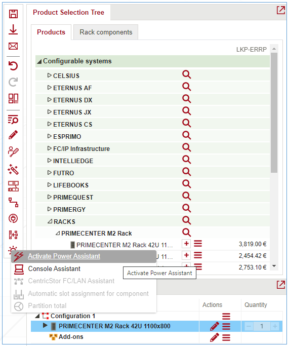
The “Activate Power Assistant” window is opened:
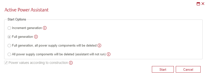
Select one of the options and click on “Start” button.
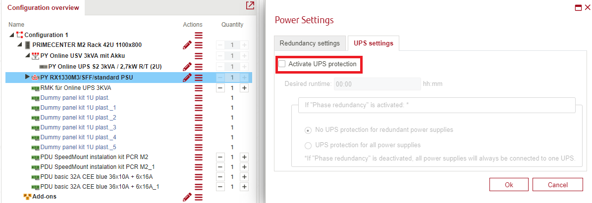
Enabling UPS protection
When a rack is equipped with an UPS without any consumer being marked as UPS secured, the assistant will show a window in which it’s possible to enable UPS protection for selected consumers.
For example, the configuration contains rack, that is equipped with an UPS, but consumer is not marked as UPS secured:
When calling Power Assistant and selecting “Increment generation” or “Full generation” option, the “UPS without UPS consumer” window is opened:
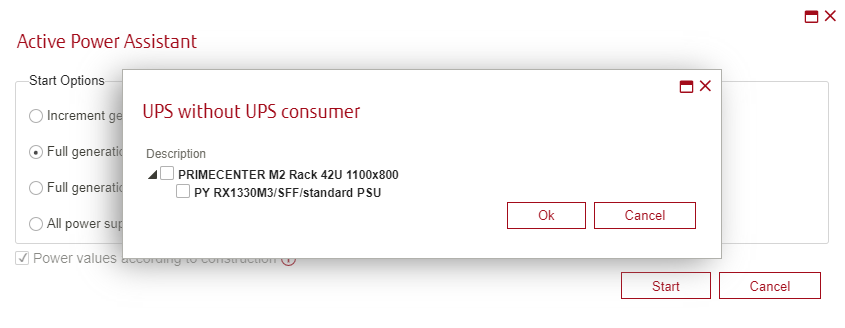
In this window it’s possible to mark consumers as secured by UPS.
Results of work
After completing the connection, the assistant will show a results window that contains data about each connected rack:
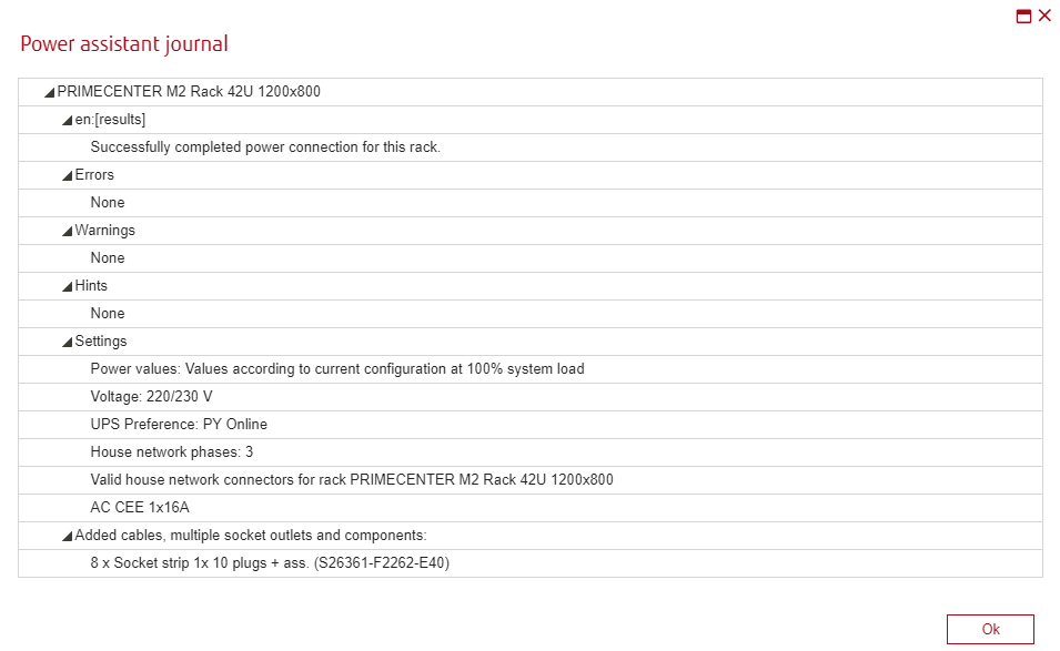
There may be errors and warnings during the work of the assistant.
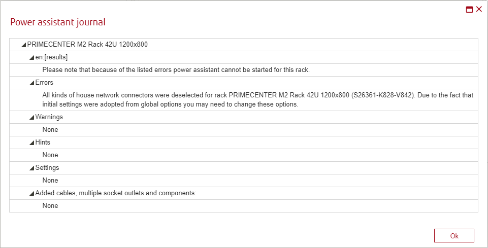
The following errors don’t allow the assistant to perform any work for a certain rack at all, in any selected option to start the assistant, except “all power supply components will be deleted (assistant will not run)” option:
No database rules found to connect component with UPS security
Different types of power supply units found in component
Consumer contains power supplies that are too small.
Incorrect number of power supplies detected for consumer
The UPS is not able to grant the required runtime
Illegal house network connector found for component
All kinds of house network connectors were deselected for rack
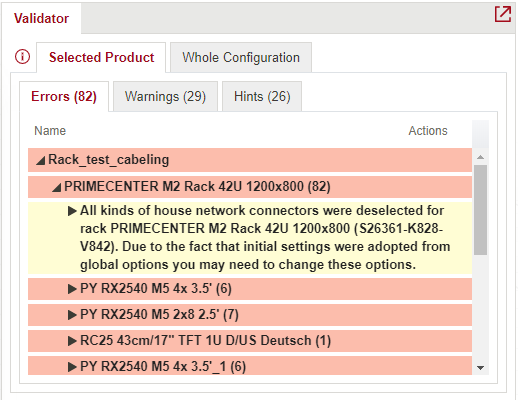
These errors are also displayed in the validator, for example:
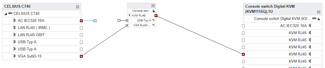
Console assistant
Console Assistant supports the user during implementing the required cabling process: connect server(s) with a console. Console can be one product with display, mouse and keyboard or it can be separate display, mouse and keyboard.
The assistant might add/delete some cables and adapters. It doesn’t impact on other functionality.
Console assistant function description
It’s possible to call console assistant for one or several racks (up to 16). These racks can be placed in one or several groups, but a group should not contain products not mounted into any rack.
Console assistant can be called to create connection:
Inside the rack(s) – between console and server(s) placed inside one rack;
Between several racks (overall) – between console and server(s) placed inside different racks (console switch is required and should be placed inside the same rack as console).
All additionally required components (cables, adapters) are added and cabled by the assistant.
A detailed journal listing all the added components is generated.
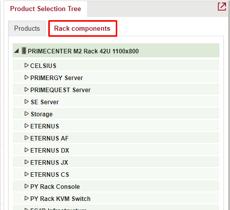
It works with servers relevant for Console assistant, which can be added into the rack from Rack components tab of the System Selection Tree.
Start the assistant
To create console connection inside rack(s), the rack should contain at least one server (console consumer), at least one console switch and only one console.
To create console connection for group of racks, each rack should contain at least one server (console consumer) and one of the racks should contain at least one console switch and only one console.
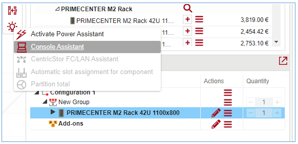
To start the assistant, select rack or group that contains rack in Configuration overview and then click on the ![]() ”Assistants / Special Functions” icon at the Action panel and select Console assistant:
”Assistants / Special Functions” icon at the Action panel and select Console assistant:
If assistant is called for one rack, results of work will be shown.
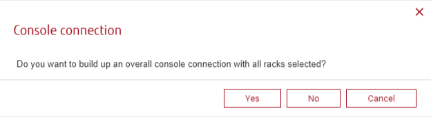
If assistant is called for group of racks, there is a Console connection modal dialog appears. Press “Yes” to create overall console connection between several racks. Press “No” to create console connection inside each rack selected:
Results of work
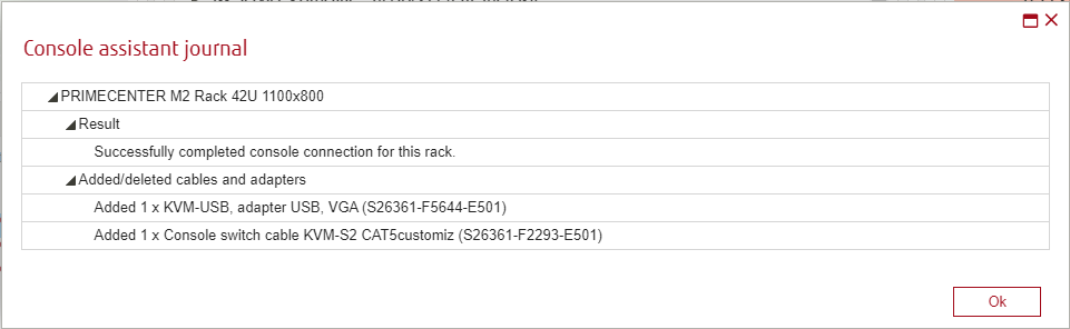
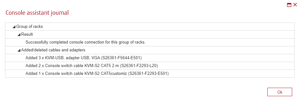
After completing the connection, the assistant will show a results window that contains data about each connected rack.
When assistant was called to connect one rack or several racks individually:
When assistant was called to connect several racks together (overall):
There may be errors and warnings during the work of the assistant. To be sure that Console assistant completes its work without errors please add the components from the Rack components tab of the System Selection tree:
There are three possible type of results of assistants work:
Console assistant successfully creates console connection and shows results in assistants journal. Created connections are visible in the Cabling view, added cables/ adapters are shown in the Configuration Overview.
Console assistant can only partially complete console connection because of some errors in the configuration’s content and shows results and error/warning messages. Created connections are visible in the Cabling view, added cables/ adapters are shown in the Configuration Overview.
Console assistant cannot complete console connection because of blocking errors in the configuration’s content and shows results and error messages.
The following errors partially block assistant’s work:
They allow the assistant to party connect products. For each reason will be shown different Error message. To solve these issues please replace components, indicated in results with components from the Rack components tab of the System Selection tree.
Possible causes for non-blocking Errors:
Some components cannot be connected.
There is at least one server. Console and all switches are in different racks, when overall connection for several racks was launched. Please replace console and switches into one rack.
There are more than one digital and at least one analog switch and there is no rule to connect these switches.
There is no rule to connect consumer with switch/ console or console with switch or cable/ adapter with console/ consumer/ switch or connector with connector.
The rules to connect switches exist, but there is no cable and/or adapter that meet these rules and existing cabling rules to connect products
Possible causes for Warning:
Cable/ adapter/ connector not found or unusable.
Mouse/ keyboard/ monitor connector not found or unusable.
No monitor/ mouse/ keyboard found.
Rack contains two or more digital switches and no analog switches. Digital switches wouldn’t be cascaded.
The following errors don’t allow the assistant to perform any work for a certain rack at all. Possible causes for blocking Errors:
Rack or included in the rack system or built-in component doesn’t exist in current database (support packs which doesn’t exist in current database shouldn’t interrupt assistants work).
Rack doesn’t contain at least one consumer.
Rack contains more than 1 consumer but doesn’t contain a switch.
There is more than one console or product with assigned “monitor” / “mouse” / “keyboard” role.
Rack contains “Virtual media” servers, but switch is not digital.
There are more consumers than number of switch ports.
Switch/ built-in cable/adapter is marked as not order relevant (select switch in WA > open context menu > uncheck “Order relevant” flag).
Number of analog switches is 32 or more, when there are no digital switches.
Number of analog switches is more or equal to number of digital switch ports.
At least one switch’s/ consumer’s / console’s connector with assigned “Console connector type” attribute is marked as reserved (to mark connector as reserved, open connection view for the product> call context menu for the connector> select “reserve” option)
One or several racks contain two or more digital switches and one or more consoles.
One or several racks contain two or more digital switches and one or more consoles and one or more consumers.
Rack contains one digital and at least one analog switch that cannot be connected to digital switch as digital switch doesn’t have unoccupied connectors, so number of Virtual Media capable connectors is not enough.
Consumer and console are in different racks, when overall connection for several racks was launched.
There is at least one server. Console and all switches are in different racks, when overall connection for several racks was launched.
There are more than one digital and at least one analog switch and there is no rule to connect these switches.
Flag values
There are three possible flags which can affect results of Console assistants work:
Order relevance
Relevant for console assistant
Virtual media
All products that can be added from the System selection tree have Order relevant status by default.
All console assistant relevant consumers have «Relevant for console assistant» flag checked and «Virtual media» flag unchecked by default.
Flags values can be changed from the context menu of product:
Changing these flags values may cause some Errors that are shown in the Console assistant journal.
New rules for Memory Modes PRIMERGY M6-models
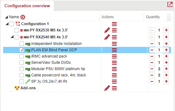
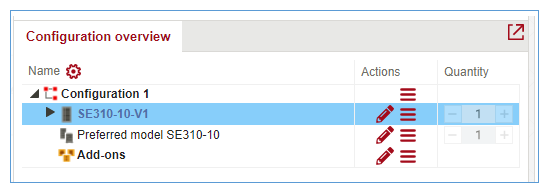
To use new functional connected with PRIMEGRY M6-model users need to add one of the following systems:
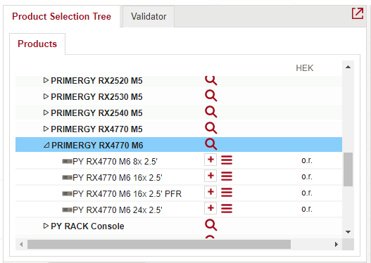
 Next, in Configure frame select Memory Modules: Installation mode and add Independent Mode Installation - PYBMMD2:
And check Validator:
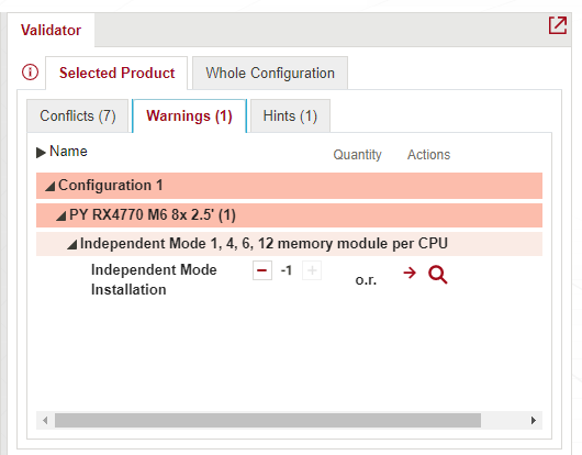
Rule states that for every:
Independent mode selected user can select 1,4,6,12 memory modules per CPU (Independent mode component – for every CPU separate independent mode needs to be selected, it is better to connect it with modes than cpu count).
Example:
1x Independent mode - possible count of memory: 1,4,6,12
2x Independent mode - possible count of memory: 2,8,12,24
3x Independent mode - possible count of memory: 3,12,18,36
4x Independent mode - possible count of memory: 4,16,24,48
Add Mirrored Channel Mode Installation - PYBMMC4 from Configure:
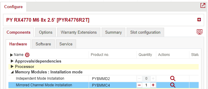
Mirroring mode selected user can select 4,6,12 memory modules per CPU (Independent mode component – for every CPU separate mirroring mode needs to be selected it is better to connect it with modes than cpu count).
Example:
1x Mirroring mode - possible count of memory: 4,6,12
2x Mirroring mode - possible count of memory: 8,12,24
3x Mirroring mode - possible count of memory: 12,18,36
4x Mirroring mode - possible count of memory: 16,24,48
«Availability» menu item
For internal users we show a mark with a red traffic light for systems in the product overview tree and the product selection assistant and for built-in components and options in the configure screen hardware with bad availability. With a mouse over on the traffic light we show the information when the system or component or options may be available again in higher quantities.
For now, WebArchitect has separate dialog where only systems, components and options are shown which are marked with a red traffic light.
This information is available for all users of WebArchitect: internal, external partners and distributors and public users But this functionality doesn’t work for the regions of APAC, Oceania and Americas.
In WebArchitect header new additional «Availability» menu item was added:
Only when a user group where the «Show availability List» flag is ticket this new menu item has to be shown.
When selecting this menu item, a full screen window should be opened with an Excel like screen that shows the columns Family, Model, Product No., description and the hint shown by a mouse over on the red traffic light. 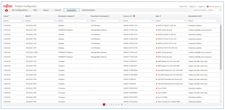
The content, which is a combination of the selected systems, built-in components and options with a red traffic light, that look like this embedded Excel file.
Also multiselect dropdown for each column is available:
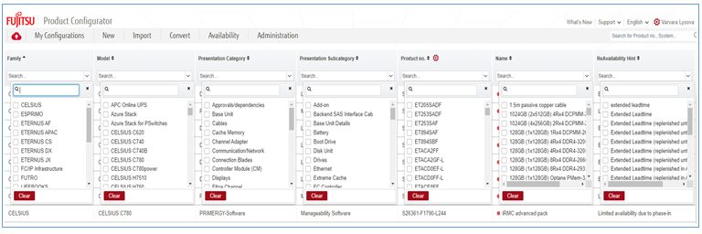
Here users can select certain Family, Model, ect. in order to find an information about needed product faster.